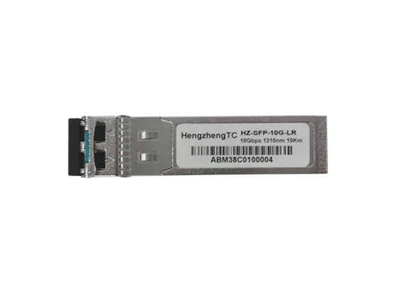
产品详情: Features· Hot Pluggable10Gb/s 10km SFP+ Optical Transceiver Module HZ-SFP-10G-LR · LC Duplex optical interface· 1310nm DFB transmitter, PIN receiver· Operating case temperature: Comme...
产品详情:
· Hot Pluggable
· LC Duplex optical interface
· 1310nm DFB transmitter, PIN receiver
· Operating case temperature: Commercial:0 to 70 °C Industrial:-40 to 85 °C
· Low power consumption
· Applicable for 10km SMF connection
· All-metal housing for superior EMI performance
· Advanced firmware allow customer system encryption
· Information to be stored in transceiver
· Cost effective SFP+ solution, enables higher port densities and greater bandwidth
· RoHS compliant (lead free)
· 10GBASE-LR/LW
· Other optical links
· IEEE 802.3ae 10GBASE-LR/LW
· SFF-8431
· SFF-8472
This 1310nm DFB 10Gbps SFP+ transceiver is designed to transmit and receive optical data over single mode optical fiber for link length 10km.
The SFP+ 10km module electrical interface is compliant to SFI electrical specifications. The transmitter input and receiver output impedance is 100 Ohms differential. Data lines are internally AC coupled. The module provides differential termination and reduce differential to common mode conversion for quality signal termination and low EMI.
Parameter | Symbol | Min | Typ | Max | Unit |
Power Supply Voltage | Vcc | -0.5 | 4 | V | |
Storage Temperature Range | Ts | -40 | 85 | °C | |
Relative Humidity - Storage | RHS | 0 | 95 | % | |
Relative Humidity - Operating | RHO | 0 | 85 | % |
Recommended Operating Conditions
Parameter | Symbol | Min | Typ | Max | Unit |
Case Operating Temperature Range | Tc | 0 | - | 70 | °C |
-40 | - | 85 | |||
Power Supply Voltage | Vcc | 3.14 | 3.3 | 3.46 | V |
Supply Current | Icc | - | - | 300 | mA |
Data Rate | BR | - | 10.3125 | - | Gbps |
Electrical Characteristics
Transmitter Electrical Characteristics | |||||
Parameter | Symbol | Min | Typ | Max | Unit |
Differential Input Voltage Swing | VIN | 180 | - | 700 | mV |
Tx Differential Input Impendence | ZIN | - | 100 | - | Ω |
Transmitter Disable Voltage | VDIS | 2.0 | - | VCC+0.3 | V |
Transmitter Enable Voltage | VEN | 0 | - | 0.8 | V |
TFAULT Logic High | VTFH | 2.4 | - | VCC | V |
TFAULT Logic Low | VTFL | VEE | - | VEE+0.4 | V |
Receiver Electrical Characteristics | |||||
Parameter | Symbol | Min | Typ | Max | Unit |
Differential output Voltage Swing | VOUT | 300 | - | 850 | mV |
Rx Differential Output Impendence | ZOUT | - | 100 | - | Ω |
LOS Assert Voltage | VLOSA | 2.4 | - | VCC | V |
LOS De-assert Voltage | VLOSD | VEE | - | VEE+0.4 | V |
![]()
Optical Characteristics
Parameter | Symbol | Min | Typ | Max | Unit | Notes |
Transmitter Characteristics | ||||||
Laser Type | DFB | |||||
Center Wavelength Range | λ | 1260 | 1310 | 1355 | nm | |
Spectral Width@-20dB | Δλ | - | - | 1 | nm | |
Side Mode Suppression Ratio | SMSR | 30 | - | - | dB | |
Launch Optical Power | Pout | -8.2 | - | 0.5 | dBm | 1 |
Extinction Ratio | ER | 3.5 | - | - | dB | |
Relative Intensity Noise | RIN | - | - | -128 | dB/Hz | |
Eye Diagram | Complies with IEEE802.3ae eye masks when filtered | |||||
Receiver Characteristics | ||||||
Receiver Type | PIN | |||||
Operating Central Wavelength | λ | 1260 | - | 1610 | nm | |
Receiver Sensitivity | Sen | - | - | -14.4 | dBm | 2 |
Receiver Overload | PSAT | 0.5 | - | - | dBm | |
Receiver Reflectance | RFL | - | - | -12 | dB | |
LOS Assert | LOSA | -30 | - | - | dBm | |
LOS De-Assert | LOSD | - | - | -17 | dBm | |
LOS Hysteresis | LOSH | 0.5 | 3 | 5 | dB | |
Notes | ||||||
1. Average power figures are informative only, per IEEE 802.3ae. 2. Measured with 231-1 PRBS@10.3125Gbps,BER<10-12 | ||||||
![]()
Pin | Symbol | Description | Notes |
1 | VEET | Transmitter Ground | 1 |
2 | TFAULT | Transmitter Fault | 2 |
3 | TDIS | Transmitter Disable. Laser output disabled on high or open | 3 |
4 | SDA | 2-wire Serial Interface Data Line | 2 |
5 | SCL | 2-wire Serial Interface Clock Line | 2 |
6 | MOD_ABS | Module Absent. Grounded within the module | |
7 | RS0 | Rate Select 0. Not Used. | 4 |
8 | RX_LOS | Loss of Signal indication. Logic 0 indicates normal operation | 2 |
9 | RS1 | Rate Select 1. Not Used. | 4 |
10 | VEER | Receiver Ground | 1 |
11 | VEER | Receiver Ground | 1 |
12 | RD- | Receiver Inverted DATA out. AC Coupled. | |
13 | RD+ | Receiver Non-inverted DATA out. AC Coupled. | |
14 | VEER | Receiver Ground | 1 |
15 | VCCR | Receiver Power Supply | |
16 | VCCT | Transmitter Power Supply | |
17 | VEET | Transmitter Ground | 1 |
18 | TD+ | Transmitter Non-Inverted DATA in. AC Coupled. | |
19 | TD- | Transmitter Inverted DATA in. AC Coupled. | |
20 | VEET | Transmitter Ground | 1 |
Notes | |||
1. Circuit ground is internally isolated from chassis ground. 2. Shall be pulled up with 4.7k-10k Ohms to a voltage between 3.15V and 3.6V on the host board. 3. Laser output disabled on TDIS >2.0V or open, enabled on TDIS <0.8V. 4. Internally pulled down per SFF-8431 Rev 4.1. | |||
![]()
![]()
Ordering information
Part Number | Product Description |
HZ-SFP-10G-LR | SFP+, 10.3125Gbps, 1310nm, SM, 10km, 0ºC~+70ºC, With DDM |
HZ-SFP-10G-LR-I | SFP+, 10.3125Gbps, 1310nm, SM, 10km, -40ºC~+85ºC, With DDM |